Flying on Instruments
Attitude (PFD)
This is the most important instrument for aeroplanes that fly at night or in cloud. This instrument shows which way is up! Here the blue indicates the sky above and the black is below the horizon. The well defined white lines indicate the wings of the plane relative to the horizon and bank angle. Here the plane is in level flight, the wings are level and the nose is on the horizon.
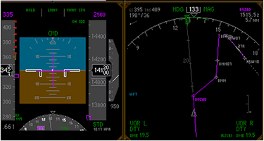
The green writing at the top displays the autothrottle (maintains airspeed, a lot more sophisticated than your car cruise control!) is in Hold. This means here that the engine power is at idle. An autopilot is flying, shown as "CMD"(see the ND above), and flying in LNAV and VNAV SPD.
This means that the autopilot is flying in a lateral navigation mode (that is, flying the magenta line as shown on the map on the ND), and flying a speed as programmed by the pilot.
At the top left hand side you can see the wind, airspeed and groundspeed. The current track is 133 degrees. Navigation aids for monitoring aircraft position are shown at the bottom left and right of the screen.
B747-400 Cockpit
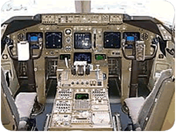 The main pilot controls and panels can be seen in this photo. As there are two pilots seated here for take-off and landing there are two "control wheels" and two sets of flying instruments.
Pilots generally take it in turns to fly sectors.
Note how the two pilots have similar instrument panel layouts. The PFDs are always on the outside, NDs are always on the inside (see below for expanation of PFD and ND). The pilots need identical sets of information to cross-check each other.
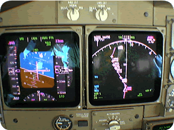 On the right is the Captain's instrument panel. The PFD (Primary Flight Display) is the left screen. Here the flight is turning to the left at 33,000 feet flying at Mach .84. The ND (Navigation Display) is the instrument on the right. This shows the map that is generated from the FMC (flight management computer).....we have three FMCs.
This map here shows my flight turning left to fly an airway just to the south of Kabul, Afghanistan.
The switches above allow for the transfer of displays. The autobrake selector is at the bottom of the ND. Brake pressure is shown under the PFD
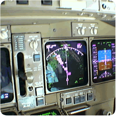 On the right is a view across to the First Officer's instrument panel. The photo is taken at a different time to the photo above.....obviously the plane is flying straight and level, that is, the wings are level. The flight is approaching New Delhi, India.
The displays are identical to the Captain's side.
The landing gear is shown in the "off" position. For landing the gear lever would be "down". After take-off when the wheels have left the runway, the gear lever is selected "up". The "off" position allows the hydraulics connected with the landing gear mechanism to be relieved of pressure.
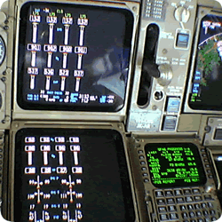 The panel view on the right shows the main engine displays on the top display. The lower display shows extra engine information. The top display is called the "EICAS" display.
(Engine Indicating and Crew Alerting System). Any problems with systems are displayed at the top right. There are none shown here. The lower EICAS is normally left blank because if there is a problem, the offending system is automatically displayed here.
The landing gear lever is shown, as is a small portion of the First Officer's instrument panel on the far right. One of the three FMCs, (Flight Management Computer), is shown bottom right.
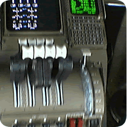 The throttles are shown on the right. You can see the lower EICAS display at the top and the First Officer's FMC at the top right.
The flap selector can be seen on the right hand side of the throttle quadrant.....here the flaps are up because we are at cruising altitude.
The white knobs of the throttles (four) can be seen in the centre of the photo. Note the four other knobs above and forward of the throttles. These are the reverse thrust levers. They can only be activated when the wheels are on the ground. Reverse thrust is a means of deflecting engine air forward, which slows the plane.